


.png)

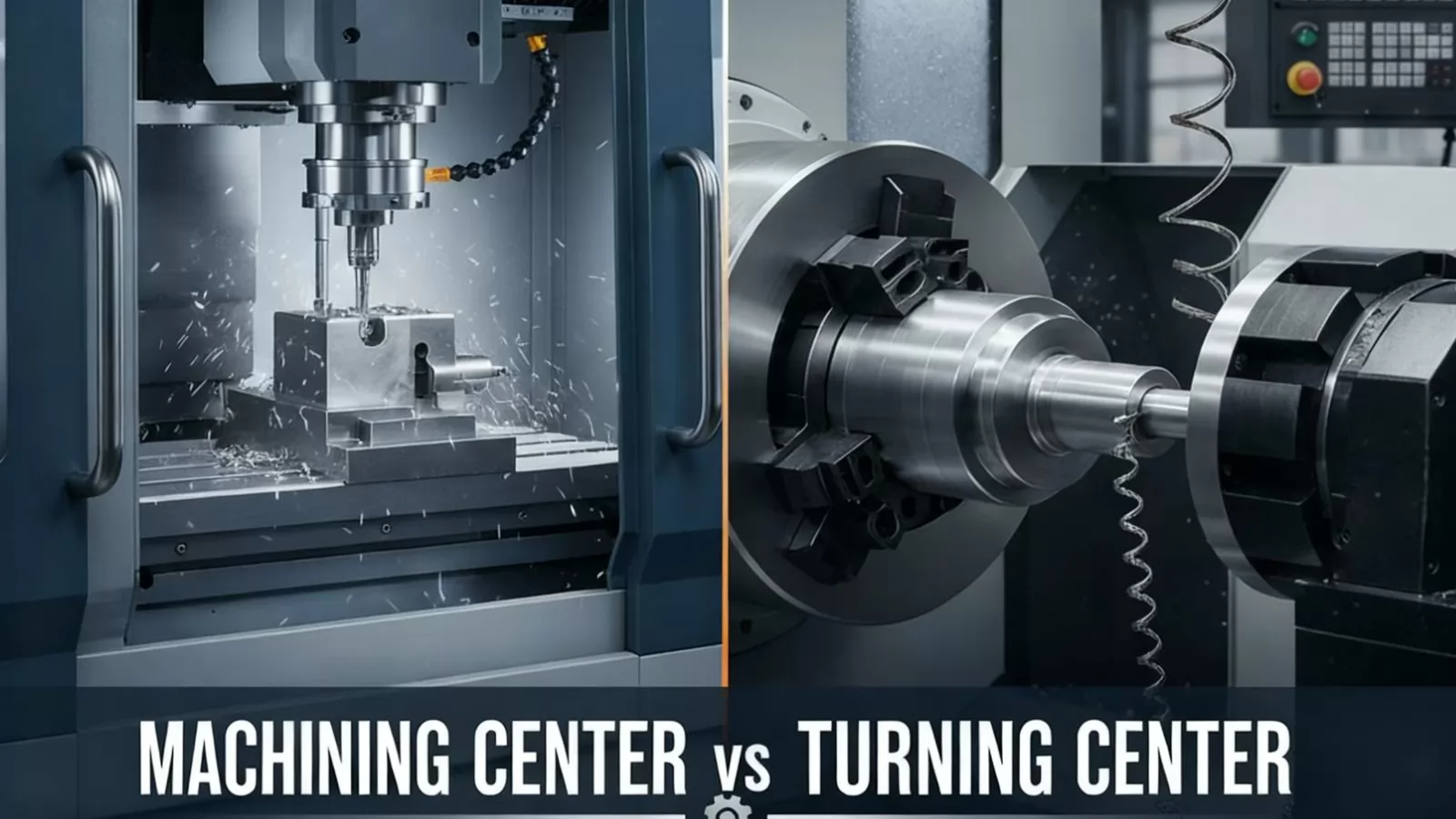
The manufacturing landscape relies heavily on Computer Numerical Control (CNC) machinery to achieve high precision and repeatable output. While the terms machining center and turning center are often used interchangeably by those new to the field, they represent fundamentally distinct classes of equipment optimized for different operational goals.
A clear understanding of these core distinctions is essential for engineers and procurement specialists when specifying equipment for new or existing production lines.
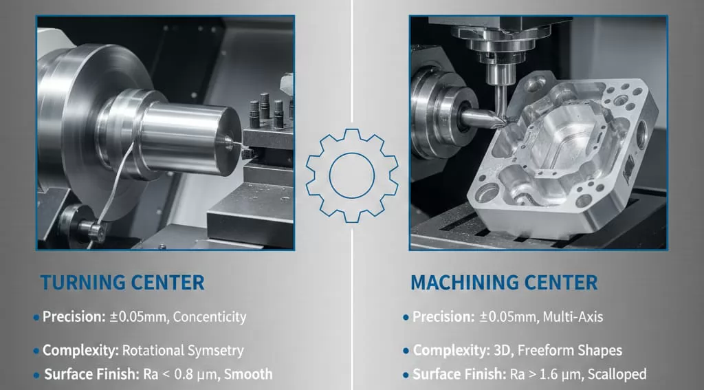
A turning center (often referred to as a CNC lathe) is primarily designed for creating cylindrical or radial parts. Its core operational principle involves rotating the workpiece at high speeds while a stationary cutting tool removes material along a defined path. The primary cutting motion comes from the rotation of the workpiece itself.
In contrast, a machining center (often referred to as a CNC mill) is designed to create complex geometric shapes by employing a rotating cutting tool (e.g., end mills, face mills, drills). The workpiece is typically held stationary on a table, and the tool performs the movement (milling, drilling, tapping, and contouring) across multiple linear axes.
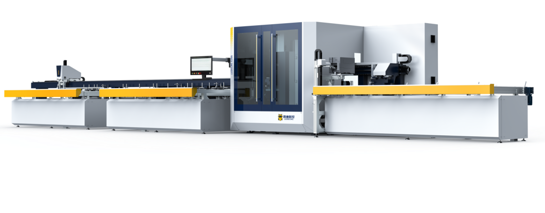
This design allows for the creation of features that lack rotational symmetry, such as pockets, slots, holes on different faces, and complex 3D surfaces. Machining centers are the backbone of many industrial processes, including the production of specialized equipment like intelligent aluminum window production lines.
Beyond the operational goals, the most significant practical differences between machining centers and turning centers lie in their structural configuration, particularly how they handle the workpiece, manage tool storage, and utilize their available axes.
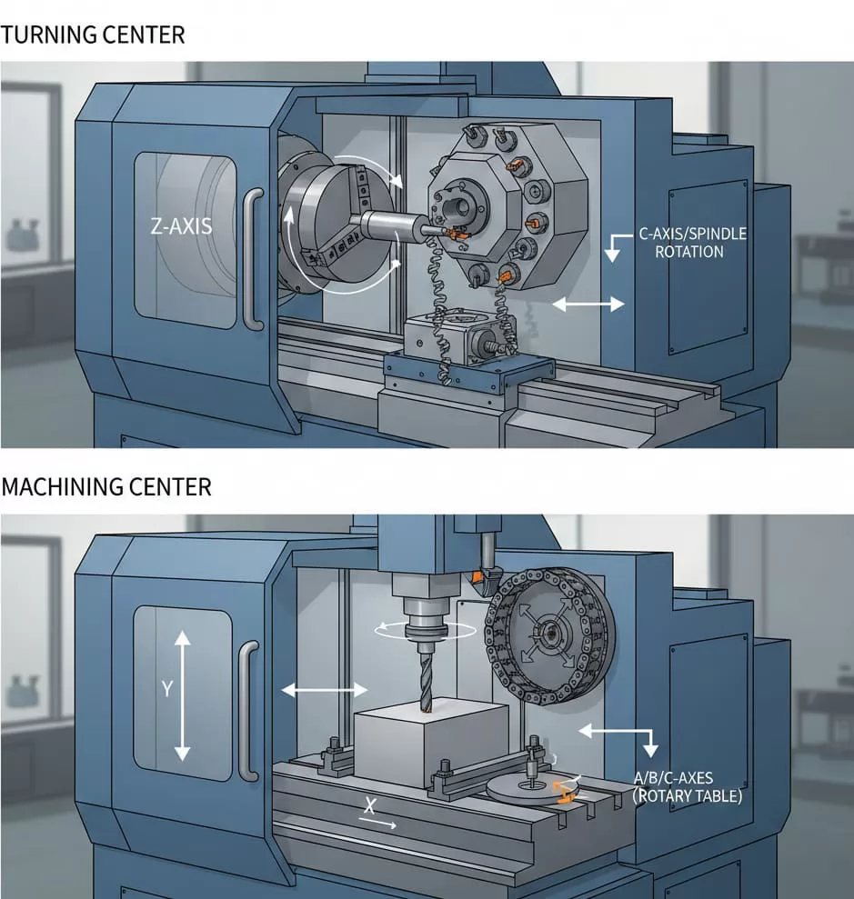
In a standard turning center, the workpiece is held by a chuck or collet attached to the main spindle, which rotates the part. The part is stationary relative to the X and Z linear axes that control the cutting tool’s position. This configuration simplifies chip evacuation for cylindrical components.
Conversely, in a machining center, the part is typically clamped securely to a stationary worktable using vices or fixtures. Material removal is achieved by moving the tool assembly around the static part in the X, Y, and Z planes. For multi-axis machining, the table itself might include a rotary axis to present different faces of the part to the cutting tool.
The method of tool management drastically impacts setup time and operational versatility:
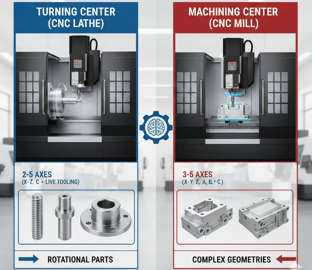
While both machines are fundamentally CNC-controlled, their axis configurations dictate the complexity of parts they can produce:
The simplest turning center operates in two dimensions (X and Z) to define the profile. Advanced models add a C-axis (spindle orientation and rotation) and potentially a Y-axis (off-center machining) to handle milling features. A basic machining center requires three axes (X, Y, Z) to mill a flat surface. Modern 5-axis machining centers utilize two rotary axes (A, B, or C) to articulate the tool or the workpiece, enabling single-setup machining of highly complex, contoured parts.
Understanding the required axis count is critical for balancing initial investment costs against the future complexity demands of the parts being manufactured.
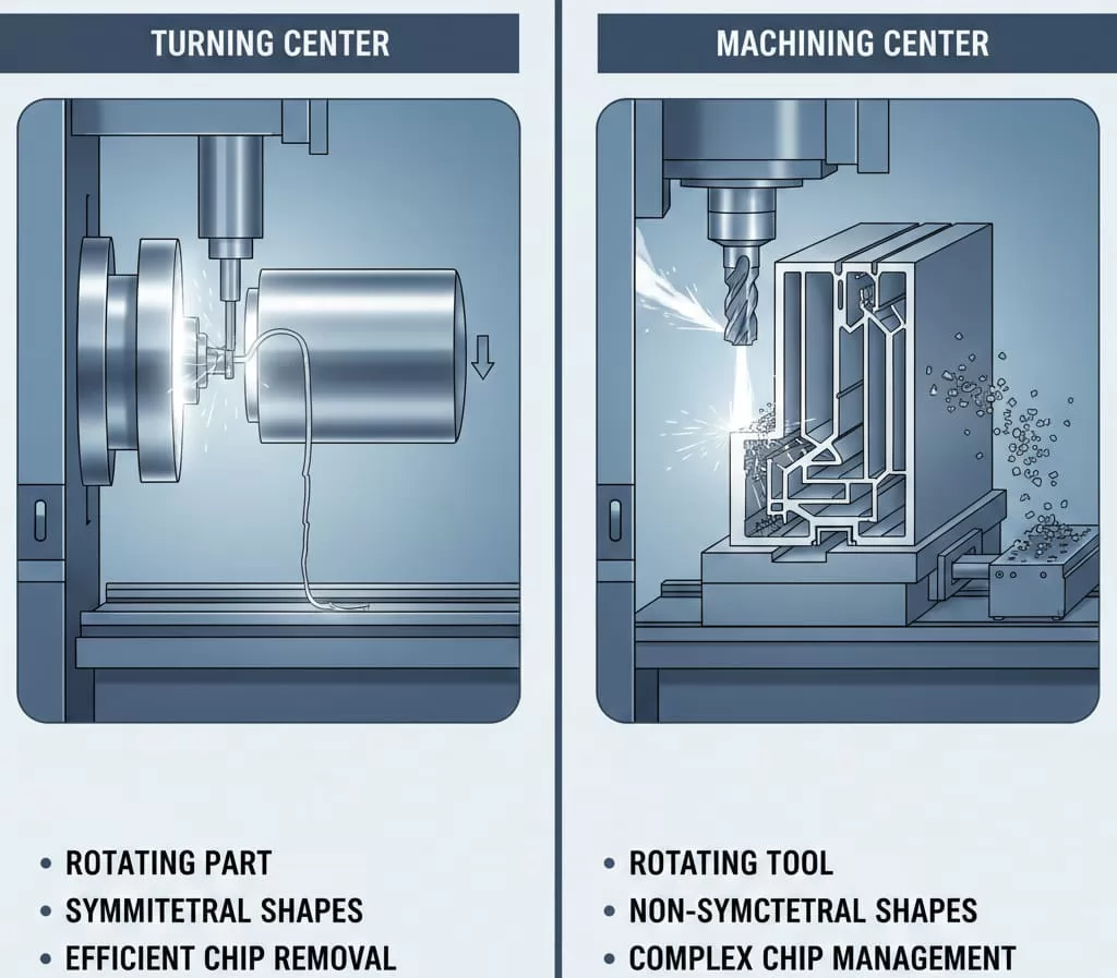
The core difference in operation boils down to which component—the workpiece or the tool—provides the primary cutting speed (or velocity). This distinction fundamentally dictates the type of geometry the machine is best suited to create.
Turning centers are specialists in rotational symmetry. The cutting force is distributed evenly as the part spins, allowing for smooth, continuous material removal to produce highly precise diameters, tapers, and threads.
Machining centers are designed for versatile, intermittent cutting actions, where the rotating tool engages and disengages the stationary material. This allows for the creation of features that involve movement across the X, Y, and Z planes simultaneously.
While both machine types handle various materials, their efficiency differs based on the cutting mechanism:
Turning centers typically manage chips easily due to gravity and the rotating motion, which often breaks the chip. Machining centers, especially when milling deep cavities or soft metals like aluminum, require rigorous coolant delivery and chip evacuation systems to prevent re-cutting chips and maintain surface integrity. For processing aluminum profiles, effective chip management in the machining center is a critical factor for long-term productivity and surface finish.
When selecting equipment for B2B industrial applications, performance metrics such as precision, attainable complexity, and final surface finish are paramount. These factors often determine whether a component meets strict engineering tolerances.
Generally, both modern turning and machining centers are capable of holding extremely tight tolerances (often within $pm 0.005$ mm or better) when properly maintained and calibrated. However, the mechanism of cutting influences precision outcomes:
The core limitation of a standard turning center is its focus on rotational symmetry. Any significant off-center features or complex pockets are challenging or impossible. This is where the machining center offers substantial versatility. The capability of 3-, 4-, or 5-axis machining allows for the creation of intricate, non-symmetrical components, deep cavities, and complex angular features required in specialized equipment and fixtures.
Surface finish quality is a function of machine rigidity, spindle speed, tool material, and feed rate, but the fundamental cutting motion plays a role:
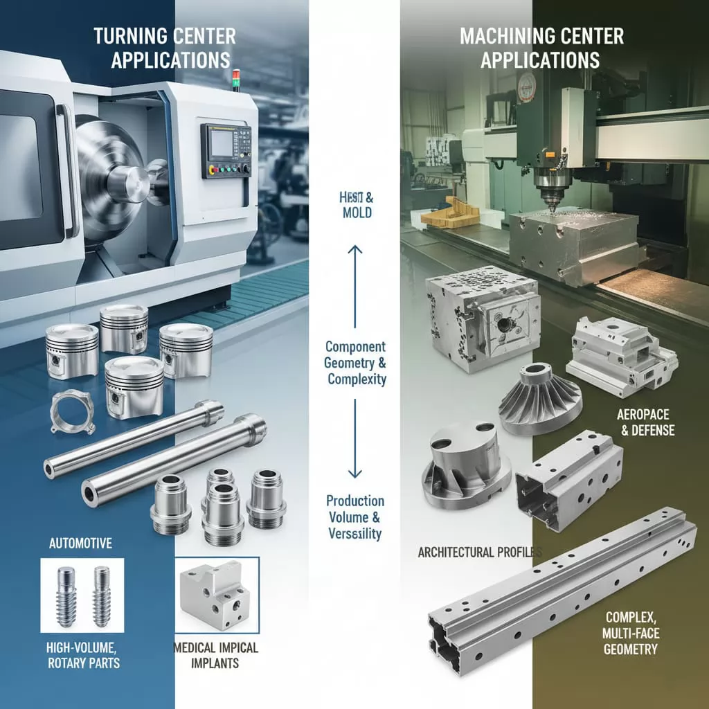
The choice between a turning center and a machining center is driven by the required component geometry, production volume, and the industry’s specific demands for precision and material handling.
Turning centers excel in industries that mass-produce standard, symmetric components where speed and consistent dimensional accuracy are paramount:
Their strength lies in rapid, high-volume production runs of parts where the majority of features are created through rotation.
Machining centers are necessary when parts require features on multiple faces, complex contours, or deep, non-symmetrical cavities. Their versatility makes them essential across numerous specialized sectors:
Machining centers offer the geometric freedom necessary for creating custom fixtures and specialized machinery components, even in low-volume, high-mix environments.
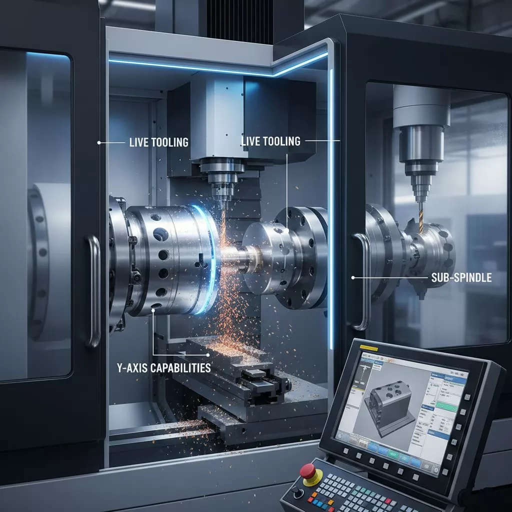
For modern, complex manufacturing, neither the pure turning center nor the pure machining center may suffice. The need to complete a part in a single setup to eliminate stacking errors, reduce handling time, and improve workflow efficiency has led to the development of Mill-Turn Centers (also known as multitasking machines).
A mill-turn center is essentially a highly advanced turning center that incorporates the full milling capabilities of a machining center. This is achieved by integrating several key features:
While the initial cost of a mill-turn center is significantly higher than a conventional machine, the efficiency gains often justify the investment, particularly for high-value components:
Reduced Setups: Parts requiring both turning (e.g., critical diameters) and milling (e.g., complex keyways or slots) can be finished entirely in one clamping. This is critical for maintaining alignment and surface integrity between features.
Error Reduction: Eliminating the need to transfer a part between a lathe and a mill drastically reduces the risk of operator error, re-chucking inconsistencies, and positional errors (stacking errors) that occur during multiple setups.
Increased Throughput: By multitasking, total cycle time is often reduced, making mill-turn technology ideal for streamlined, high-efficiency manufacturing cells producing complex parts for aerospace, medical, and specialized machinery industries.
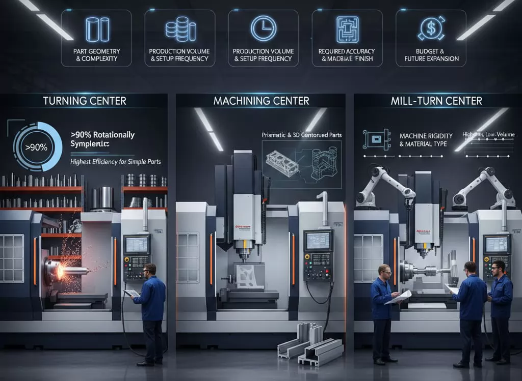
The final decision between a turning center, a machining center, or a hybrid mill-turn solution requires a thorough assessment of current and projected manufacturing needs. Engineers and procurement teams should consider five primary criteria before investment.
For very high volumes of simple parts, dedicated machines (a turning center for symmetric parts, or a high-speed machining center for continuous milling) often provide the lowest cost per part. If the production involves high-mix, low-volume runs of complex parts requiring both turning and milling, a Mill-Turn Center is usually the most economical choice due to the substantial reduction in setup time.
If features demand ultra-high concentricity and surface smoothness on diameters, the inherent stability of the turning process is superior. If maintaining tight tolerances across large, complex prismatic features is required, a high-rigidity 5-axis machining center is necessary.
The rigidity of the machine is crucial, especially when working with challenging materials (e.g., titanium, tool steel). Machining centers generally have heavier, more robust base castings to handle the higher dynamic loads involved in intermittent milling. Conversely, when processing softer materials like aluminum profiles, the emphasis shifts toward high spindle speed, rapid axis movement, and exceptional chip management.
While basic turning centers and 3-axis machining centers represent a lower initial capital outlay, the long-term flexibility offered by 5-axis machining centers or Mill-Turn machines often provides a better return on investment by future-proofing the facility against evolving component complexity.
A strategic investment decision must align machine capability with the most demanding part in the production portfolio to ensure that the equipment can handle the full spectrum of required manufacturing tasks.
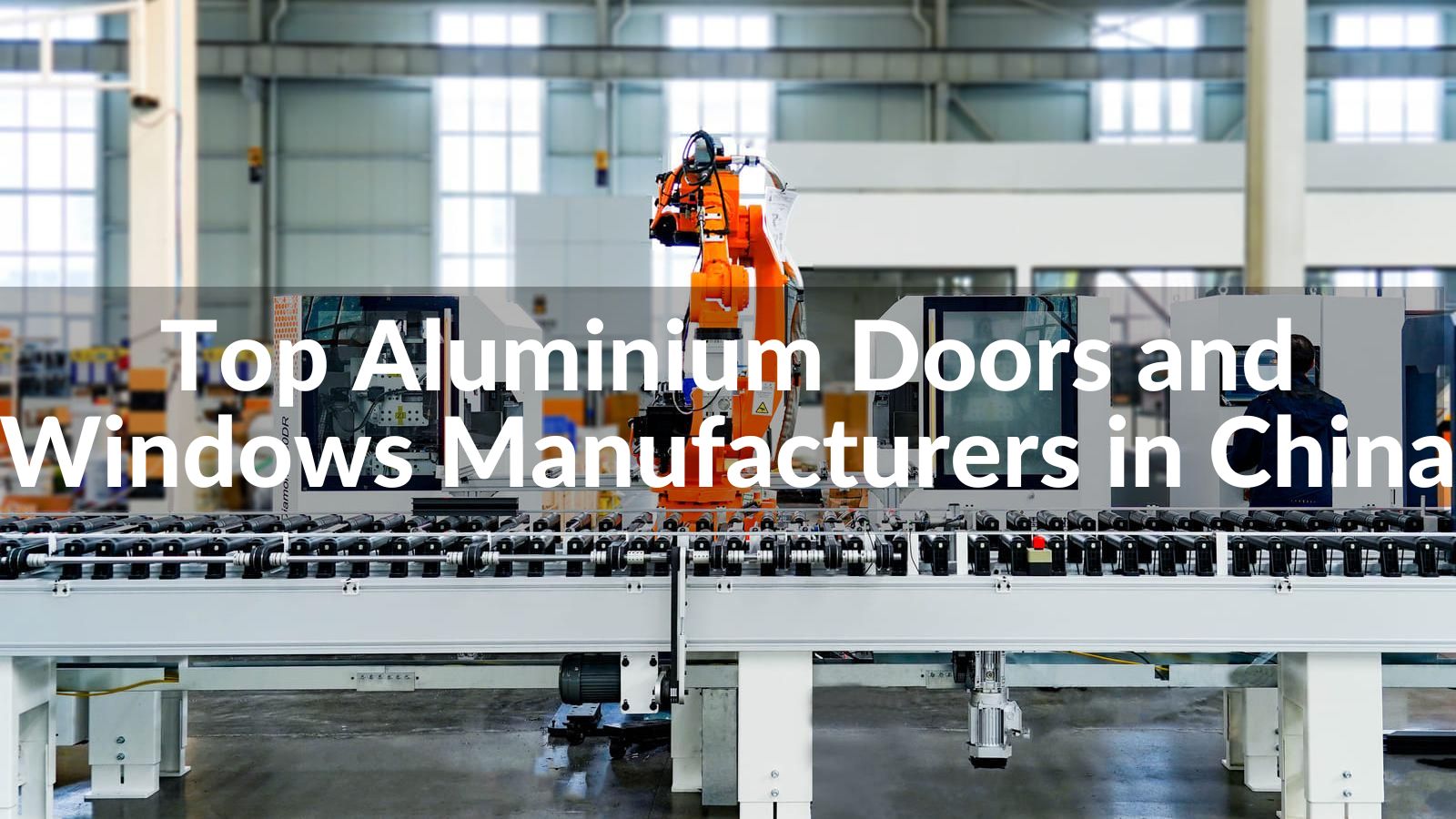

Discover the top 10 aluminium doors and windows manufacturers in China for 2026, including OPPEIN, Mannlee, and Paiya. Explore their innovative aluminium solutions, from energy-efficient windows to luxury doors, backed by LEADCNC’s advanced production lines.
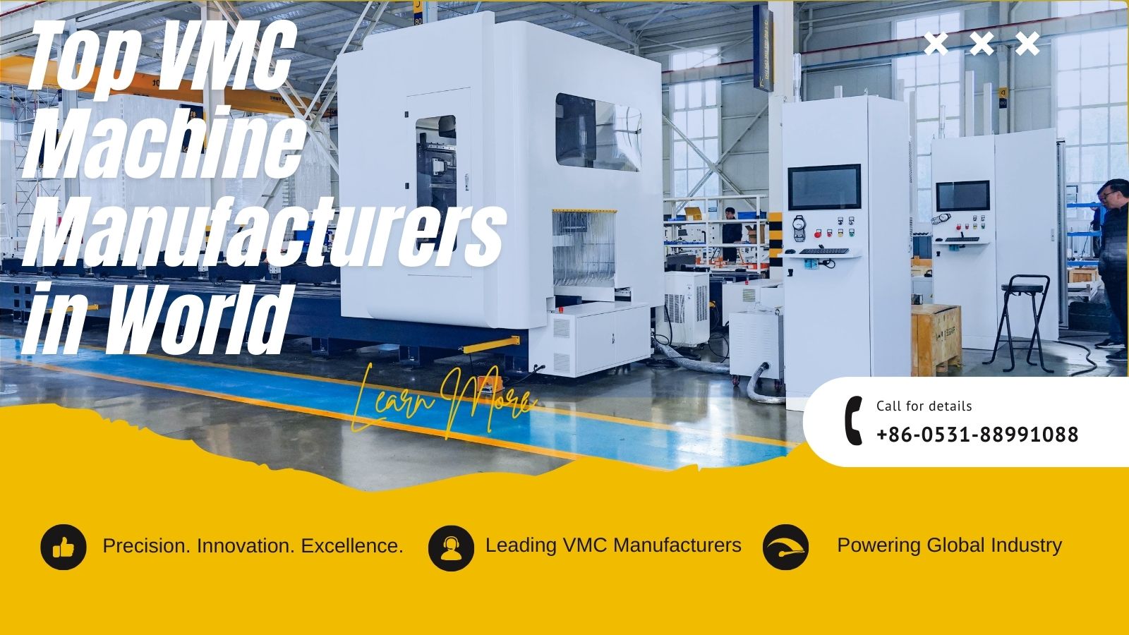
Discover 2025's top 10 VMC machine manufacturers worldwide. Compare leading brands for innovation, reliability and value to find your ideal vertical machining center.

Understand the key differences between machining centers and turning centers. A guide for engineers and procurement on operational capabilities, precision, and selection criteria for CNC equipment.
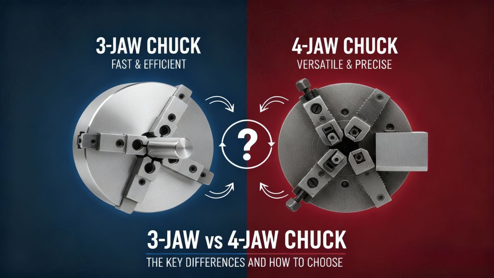
Compare 3-jaw vs 4-jaw chucks for turning operations. Learn the differences in self-centering, precision (runout), setup time, and how to choose the optimal chuck for high-volume or irregular workpieces.


.png)