


.png)

The Computer-Aided Design (CAD) file is the foundation and blueprint for any Computer Numerical Control (CNC) machining operation. It is not merely a visual representation; it is the definitive, mathematically precise source of truth that dictates the final geometry, tolerances, and surface finish of the machined part. In a B2B manufacturing context, the integrity and preparation of the CAD file directly translate into production efficiency, material waste minimization, and, most importantly, the assurance of component quality and fit.
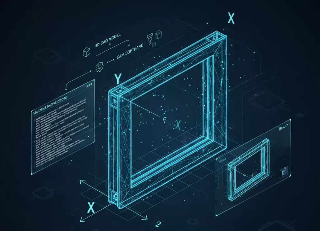
The journey begins when the design engineer translates the required product specifications (form, fit, and function) into a 3D CAD model. This model contains all necessary geometric data—lines, planes, curves, and surfaces—which will be consumed by the Computer-Aided Manufacturing (CAM) software. The CAM system uses this precise data to generate the numerical code (G-code and M-code) that controls the movement of the CNC machine's tools. Any ambiguity, error, or missing information in the CAD file will propagate downstream, resulting in faulty G-code, machine collisions, or parts that fail quality checks. For high-precision applications, such as components in an intelligent aluminum window production line, an imperfect CAD model can lead to significant bottlenecks and expensive reworks. The CAD file, therefore, acts as the contract between the design team and the manufacturing floor.
A crucial element embedded within the CAD model is the definition of the part's coordinate system and datums. The coordinate system must be aligned with how the part will be mounted or "fixtured" on the CNC machine table. This alignment is critical because the CAM software needs a stable reference (the Machine Zero) from which all toolpaths are calculated. Poorly defined or misaligned coordinate systems are a common cause of dimensional inaccuracies and require complex, manual offsets by the machine operator, which introduces risk. For successful CNC operation, the CAD file must clearly define the $X$, $Y$, and $Z$ axes relative to the part geometry and the intended machining process.
When transitioning a design from the CAD environment to the CAM system, the choice of file format is paramount. The format dictates how geometric, topological, and metadata are communicated. In B2B CNC machining, specific vendor-neutral and proprietary formats are recognized as industry standards due to their ability to accurately retain complex model information.
For interoperability between different CAD and CAM software suites, vendor-neutral formats are essential. They serve as the universal language of digital manufacturing:
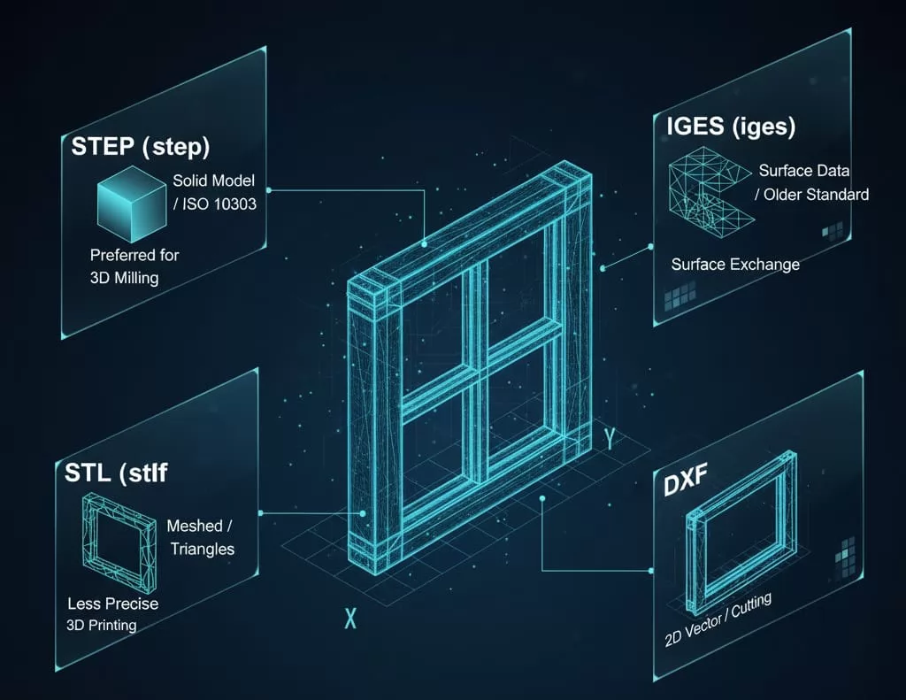
STEP (.step or .stp): The Standard for the Exchange of Product model data, governed by the ISO 10303 standard. STEP is the most robust and preferred format for B2B exchange. It captures the exact geometry (NURBS) and crucial topological information (such as faces, edges, and surfaces), ensuring the model is transferred as a "Solid Model" rather than just a collection of graphical data. This exact representation is critical for complex 3D and multi-axis machining applications, including the precise profiling required for aluminum window components.
IGES (.igs or .iges): The Initial Graphics Exchange Specification is an older standard that primarily handles surface geometry. While still widely supported, IGES files are more prone to surface continuity errors (gaps or overlaps) when complex solids are exported. It is often used when surface data is prioritized over true solid representation, but it is generally being superseded by STEP for robust solid modeling.
While STEP and IGES contain precise geometric definitions, formats based on triangulated mesh data are less ideal for high-precision machining because they approximate surfaces rather than defining them mathematically.
STL (.stl): The standard format for Stereolithography (3D Printing). STL files represent solid geometry using a mesh of connected triangles. While useful for rapid prototyping and sometimes basic 3-axis machining, the approximation inherent in the mesh makes it unsuitable for projects requiring tight tolerances or complex surface finishes, as the CAM software must interpret the polygonal facets rather than the true curved surface.
DXF/DWG (.dxf or .dwg): These are primarily 2D drawing formats, though they can sometimes carry 3D data. They are crucial for 2D machining operations like waterjet cutting, laser cutting, or simple profile milling (e.g., nesting optimization for flat stock). They accurately define lines, arcs, and polylines but lack the robust volume information of a solid model.
| Format | Type | Primary Use Case in CNC | Key Advantage |
|---|---|---|---|
| STEP | Solid/NURBS | Preferred Standard for 3D Milling | Maintains true solid integrity and topological data. |
| IGES | Surface/NURBS | Exchange where surface data is dominant | Widely accepted, handles complex curves/surfaces. |
| STL | Mesh/Faceted | Basic machining; used heavily in 3D Printing | Quick file generation; simple visualization. |
| DXF | 2D/Vector | Profile cutting and 2.5D operations | Excellent for flat pattern geometry and nesting. |
For CNC machining, the differentiation between solid modeling and surface modeling in CAD files is not merely academic; it fundamentally impacts how the CAM software generates toolpaths and verifies material removal. B2B precision manufacturing heavily relies on true solid geometry for reliable results.
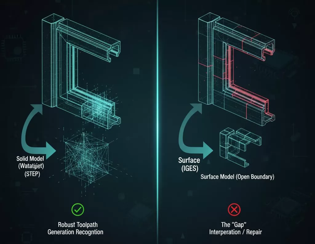
A Solid Model (typically found in STEP, Parasolid, or native CAD formats) defines the entire volume of a part. It is a "watertight" representation, meaning the model is closed, has a defined interior and exterior, and possesses complete topological information—data on faces, edges, and vertices that connect seamlessly.
Robust Toolpath Generation: CAM software can reliably calculate tool offsets and verify stock removal because it knows exactly where the material is and where it is not. This prevents the toolpaths from accidentally entering the intended void areas.
Feature Recognition: Solid models often retain the intelligence of the features used to create them (e.g., holes, fillets, pockets). This allows CAM software to automatically recognize standard features and apply optimized machining strategies, such as canned drilling cycles or 2.5D pocketing.
Boolean Operations and Verification: Only true solid models allow for reliable Boolean operations (adding or subtracting material) and accurate collision detection, which is vital during complex multi-axis simulation.
A Surface Model (common in IGES or complex freeform designs) defines only the boundary of the part—the skin—without explicitly defining the interior volume.
The "Gap" Problem: The primary issue with surfaces is the risk of "seams" or "gaps" between adjacent surfaces. If the CAM system encounters a non-watertight boundary, it cannot reliably distinguish between solid material and empty space, leading to incomplete or incorrect toolpaths (e.g., the toolpath might "leak" through the perceived gap).
Focus on Complex Forms: Surface modeling is often necessary for highly organic, aesthetic, or complex curved geometries that are difficult to define with solid modeling primitives (common in aerospace or medical device molds). However, extra care must be taken to ensure the surfaces are "knitted" or "merged" seamlessly before export.
Manual Interpretation: When working with surface files, the CAM programmer often has to spend significant time manually "healing" or repairing the model to create a usable solid body before programming can begin, adding non-value-added time and potential for error.
| Feature | Solid Model (STEP) | Surface Model (IGES) |
|---|---|---|
| Volume Definition | Defines complete, verifiable internal volume | Defines only the boundary (the skin) |
| Integrity | Watertight and topologically sound | Prone to gaps, overlaps, or open edges |
| CAM Reliability | High; allows for accurate stock simulation | Medium; often requires manual repair/knitting |
| Toolpath | Uses feature recognition for efficiency | Requires defining toolpaths based on surface curves |
A CAD file may be geometrically correct according to design intent, but it may not be machinable. Preparing a CAD model for CNC involves incorporating manufacturing considerations directly into the design to prevent non-conformance and reduce machining time. Engineers and designers must address several key geometric factors before releasing the file to the manufacturing floor.
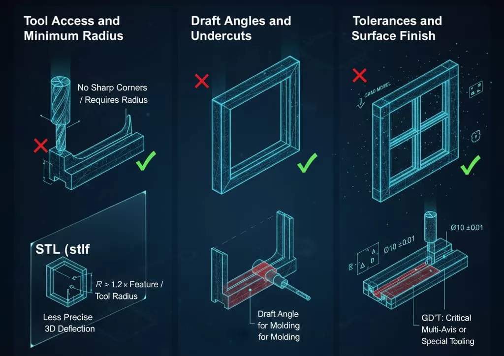
CNC machining relies on cylindrical cutting tools. Therefore, any internal corner in a part must have a radius, not a sharp 90-degree corner, to accommodate the tool’s geometry.
Internal Radii: The minimum internal radius should always be slightly greater than the radius of the smallest standard end mill intended for the feature. A common guideline is to specify a corner radius that is at least $1.2 times$ the tool radius. Specifying sharp internal corners forces the use of prohibitively small tools, which are slow and prone to breakage, or necessitates expensive EDM (Electrical Discharge Machining) post-processes.
Aspect Ratio and Depth: Deep, narrow features (high aspect ratio) present challenges. As the cutting tool extends further from the spindle, its rigidity decreases, leading to deflection, chatter, and poor surface finish. The CAD model should ideally feature wall depths that allow for stable tool engagement.
While not always applicable, certain manufacturing processes require specific design elements:
Draft Angles: For parts intended to be molded or cast before final machining, positive draft angles are essential to facilitate ejection. While pure CNC milling can handle vertical walls, designs optimized for manufacturing systems like injection molding or die casting (relevant to complex aluminum profiles) must include appropriate draft.
Undercuts and Cavities: Features that cannot be reached by the cutting tool from the primary setup axis are defined as undercuts. While 3-axis CNC cannot access these areas, the CAD design must clearly indicate features that require specific tooling (like T-slot cutters) or require the use of multi-axis (4- or 5-axis) machining centers for simultaneous contouring. If the part is designed for simpler 3-axis work, undercuts must be avoided or redesigned for accessibility.
The CAD model is the ideal geometric representation, but manufacturing reality involves tolerances. These must be clearly defined within the associated technical drawings or directly within the CAD file (using Product Manufacturing Information - PMI).
Geometric Dimensioning and Tolerancing (GD&T): Using GD&T ensures critical features are toleranced appropriately. Machining every feature to extremely tight tolerance is costly and unnecessary. The CAD model must reflect the features that require high precision (e.g., bore locations for mating parts) versus those that can have looser tolerances.
Surface Finish: The required surface finish (measured by $R_a$ or $R_{z}$) impacts the final machining strategy, speed, and cycle time. If the CAD model requires a specific finish (e.g., $text{Ra } 0.8 mutext{m}$ for sealing surfaces), this information must be included to guide the selection of finishing toolpaths.
Before a CAD file is released for manufacturing, a rigorous preparation and clean-up protocol is essential. These practices ensure the model is robust, interpretable by the CAM software, and optimized for generating efficient G-code, thereby avoiding costly delays and machine downtime.
The transition between different software platforms (e.g., from design CAD to CAM system) can sometimes introduce small, non-manifold geometry errors that are invisible in the original CAD environment but disrupt toolpath calculation.
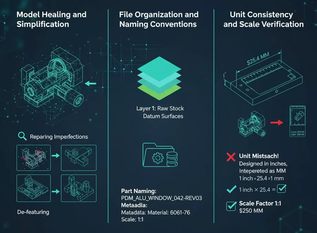
Repairing Imperfections: Always run a geometric analysis or "healing" function to check for common issues:
Non-Manifold Edges: Edges shared by more than two faces.
Tiny Faces or Slivers: Excessively small geometric entities that confuse the meshing or toolpath algorithms.
Open Boundaries: Ensure the model is completely "watertight" if it is intended to be a solid body (critical when working with imported IGES or STEP files).
De-featuring: Remove non-essential geometric details that do not affect the functionality of the part but add complexity and time to the CAM process. This includes tiny aesthetic chamfers, vendor logos, internal threads that will be tapped post-machining, or minor fillets in non-critical areas. Simplifying the geometry allows the CAM system to calculate toolpaths faster and more reliably.
Clear documentation and organization within the CAD file are crucial for streamlined B2B workflow and traceability, especially when dealing with complex assemblies (such as those for specialized window production machinery).
Layer Management: Utilize layers or colors to segregate different machining features. For instance, put raw stock geometry on one layer, critical datum surfaces on another, and areas requiring special finishing on a third. This aids the CAM programmer in quickly selecting relevant geometry for specific operations.
Part Naming and Metadata: The CAD file name should adhere to the established company PDM (Product Data Management) or ERP (Enterprise Resource Planning) naming structure. Embed crucial metadata, such as material type, revision number, and scale factor, directly into the file's properties. This prevents ambiguity and ensures the correct revision is manufactured.
A fundamental error that leads to complete manufacturing failure is unit mismatch.
Standardized Units: Verify that the model is exported using the intended units (millimeters or inches). A model designed in inches but interpreted by the CAM software as millimeters will result in a part scaled down by a factor of 25.4, leading to immediate waste.
Scale Factor: Always check that the scale factor upon export is $1:1$. It is best practice to have the CAM programmer quickly verify a critical dimension (e.g., overall length) against the technical drawing immediately upon importing the CAD file.
The final procedural step before programming begins is the accurate export and transfer of the prepared CAD file into the CAM environment. This transition requires attention to settings to ensure data integrity and geometric accuracy are maintained.
When exporting the CAD file, particularly into a universal format like STEP, the settings used can significantly affect the quality of the imported data.
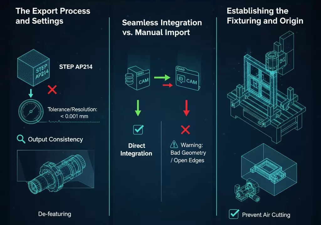
Format Selection: As established, use STEP AP203 or STEP AP214 for solid models. AP214 is generally preferred as it supports color, layers, and geometry validation properties, which can be useful for visualization and feature identification in the CAM system.
Tolerance/Resolution: Some CAD packages allow the user to specify the export tolerance (sometimes called chord height or facet deviation). For precision machining, this tolerance should be set to a value significantly smaller than the tightest machining tolerance required (e.g., $0.001 text{ mm}$ or $0.00005 text{ in}$) to ensure the mathematical surfaces are accurately represented. A coarser tolerance results in an approximated model.
Output Consistency: Ensure that only the relevant geometric body is exported. If the CAD file contains multiple part configurations, tooling geometry, or assembly fixtures, these must be suppressed or hidden before export to avoid confusing the CAM system.
B2B manufacturing environments often leverage integrated CAD/CAM suites, which streamline the transfer process:
Direct Integration: If the CAD software and CAM software are modules of the same platform, the transfer is typically instantaneous and lossless. This method ensures that the original feature intelligence and parametric data are retained, allowing the CAM programmer to reference features directly rather than just raw geometry.
Neutral File Import: When using separate software (e.g., SolidWorks to Mastercam), the neutral file (STEP/IGES) must be imported. The CAM programmer must carefully review the import log for warnings about "bad geometry," "stitch errors," or "open edges." Any such warning indicates a potential issue that needs to be resolved by healing the model within the CAM system or requesting a revised file from the designer.
The transferred CAD model needs to be oriented and positioned correctly relative to the physical machine setup:
Part Origin Confirmation: In the CAM environment, the programmer must verify that the coordinate system defined in the CAD model (Part Zero) aligns perfectly with where the part will be fixtured on the machine (Machine Zero). This alignment often involves moving or rotating the model within the CAM system to match the anticipated machine setup (e.g., aligning the $Z$-axis normal to the primary machining face).
Stock Definition: The final transfer step is defining the raw material stock. The CAD model defines the final part geometry, but the CAM system needs the starting stock geometry to calculate optimal material removal paths. The stock definition must accurately reflect the size, shape, and placement of the raw billet or casting to prevent air cutting or, worse, running a finishing tool into excessive stock material.
Even with advanced software, CAD file errors are a leading cause of production delays and costly rework in CNC machining. Recognizing and systematically eliminating these specific errors is crucial for maintaining a high-efficiency B2B manufacturing workflow.
These errors relate directly to the integrity of the 3D model itself and are most problematic when importing vendor-neutral files.
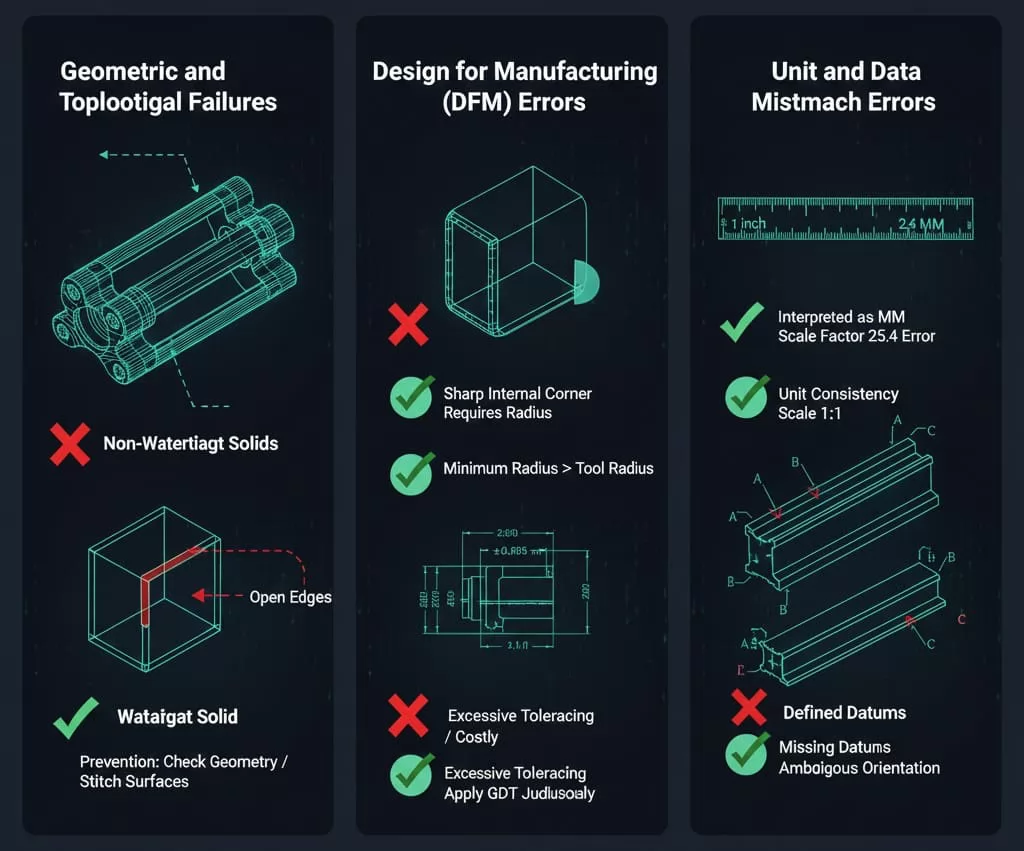
Non-Watertight Solids (Open Edges): This occurs when surface patches fail to join perfectly, leaving microscopic gaps. As discussed, this prevents the CAM software from defining a clear volume, often halting the solid-based toolpath calculation.
Prevention: Always export using high-quality STEP settings. Use the built-in "Check Geometry" or "Stitch Surfaces" tools in both the CAD and CAM software to verify closure before proceeding.
Corrupted or Invalid Geometry: Sometimes, complex operations (like blends or sweeps) can result in surfaces with zero area or self-intersecting loops. These are mathematically invalid and lead to CAM failure.
Prevention: Simplify the problematic feature or rebuild it using a different modeling approach. Isolate and delete faces that are too small ("sliver faces").
These errors occur when the design is geometrically sound but physically impossible or highly impractical to machine with standard tooling.
Sharp Internal Corners (Zero Radius): As highlighted previously, a zero radius corner requires either a sharp internal corner tool (which doesn't exist) or a corner radius that is smaller than the tool used, which results in non-conformance.
Prevention: Ensure all internal corners have a radius larger than the smallest end mill the factory is willing to use, ideally with a standard stock radius for cost optimization.
Excessive Tolerancing: Specifying overly tight tolerances (e.g., $pm 0.005 text{ mm}$ for a non-critical feature) significantly increases cycle time and inspection costs, often requiring expensive specialized machinery.
Prevention: Apply GD&T judiciously. Only tight tolerance critical features related to part function, assembly, or sealing (e.g., linear guides on aluminum profiles).
These are simple but catastrophic clerical errors that can scrap large batches of material.
Unit Misinterpretation: A model created in millimeters being read as inches, resulting in a scale factor error of $25.4$.
Prevention: Explicitly state the intended units in the filename and technical drawing. Upon import, the CAM programmer must immediately measure a known dimension on the model to confirm the scale.
Missing or Ambiguous Datums: If the CAD file doesn't clearly define the primary datums (A, B, C) for fixturing, the CAM programmer must guess the intended orientation, leading to potential alignment errors.
Prevention: Define a clear coordinate system within the CAD model aligned with the intended primary clamping face. Ensure the technical drawing clearly references these datums for measurement.
For sophisticated B2B operations, particularly those involving large components or complex motion control—such as the intelligent aluminum window production lines manufactured by LeadCNC—standard 3-axis CAD preparation must be augmented with specific considerations for scale, stability, and advanced kinematics.
Machining components that exceed the typical small-part envelope introduces challenges related to thermal stability and cumulative error.
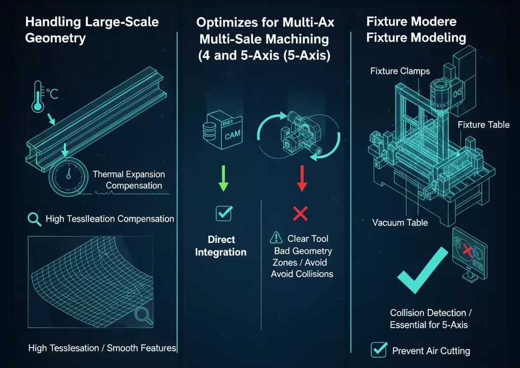
Thermal Expansion Compensation: Large metal parts, especially aluminum, are highly susceptible to thermal expansion during machining. A CAD model created at $20^circ text{C}$ may need geometric compensation if it will be machined in an environment where the temperature varies significantly. Although compensation is usually handled in the CAM/Post-Processor, the designer must be aware of the operational temperature of the final part and communicate this.
Tessellation/Faceting for Large Files: When converting large, high-detail CAD models to mesh formats for certain simulations, the resulting file size can be massive. For STEP exports, maintaining the highest possible geometric accuracy ensures that features remain smooth across the entire length, preventing the accumulation of error that might manifest as rough toolpaths over several meters of travel.
Multi-axis machining utilizes simultaneous rotation and translation to access complex geometries and complete a part in fewer setups, dramatically increasing efficiency but requiring more complex CAD preparation.
Clear Tool Access Zones: In a 5-axis CAD model, the designer must consider the physical constraints of the machine spindle and rotary tables. The geometry should allow for the necessary tool tilt and reach without causing collisions between the tool holder, the machine head, and the fixturing clamps. Unnecessary complexity or confined deep pockets should be flagged for review.
Surface Continuity for Finishing: 5-axis contouring relies on the perfect mathematical continuity of the model surfaces. Imperfections in the surface (tiny gaps or tangent discontinuities) that might be ignored in 3-axis roughing will cause visible stuttering or abrupt changes in the tool vector during high-speed 5-axis finishing. The CAD model surfaces must be meticulously tangent and curvature continuous ($G^2$ or better) in critical areas.
Fixture Modeling: For complex 5-axis work, the CAD file provided to the CAM programmer must often include the model of the fixturing clamps, vises, or vacuum tables. This is essential for the CAM software’s collision detection routine, preventing the tool from colliding with the holding devices during dynamic multi-axis movements.
By addressing these advanced geometric and logistical challenges directly in the CAD file, manufacturers can leverage the full potential of multi-axis and large-scale CNC equipment, producing highly precise components like those used in complex automated production systems.


Discover the top 10 aluminium doors and windows manufacturers in China for 2026, including OPPEIN, Mannlee, and Paiya. Explore their innovative aluminium solutions, from energy-efficient windows to luxury doors, backed by LEADCNC’s advanced production lines.

Discover 2025's top 10 VMC machine manufacturers worldwide. Compare leading brands for innovation, reliability and value to find your ideal vertical machining center.
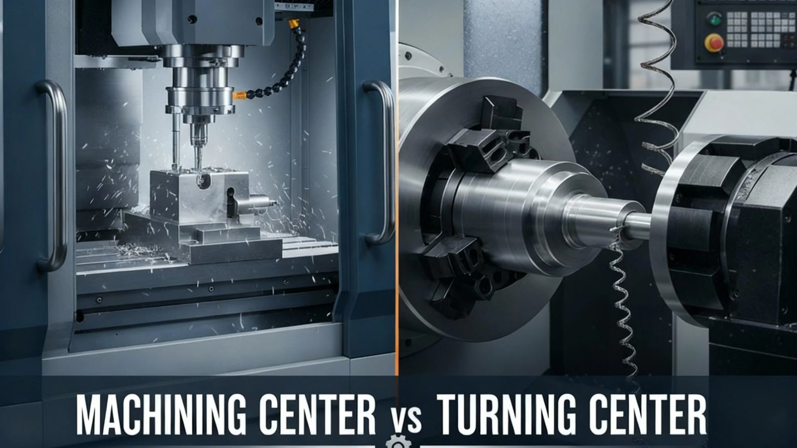
Understand the key differences between machining centers and turning centers. A guide for engineers and procurement on operational capabilities, precision, and selection criteria for CNC equipment.
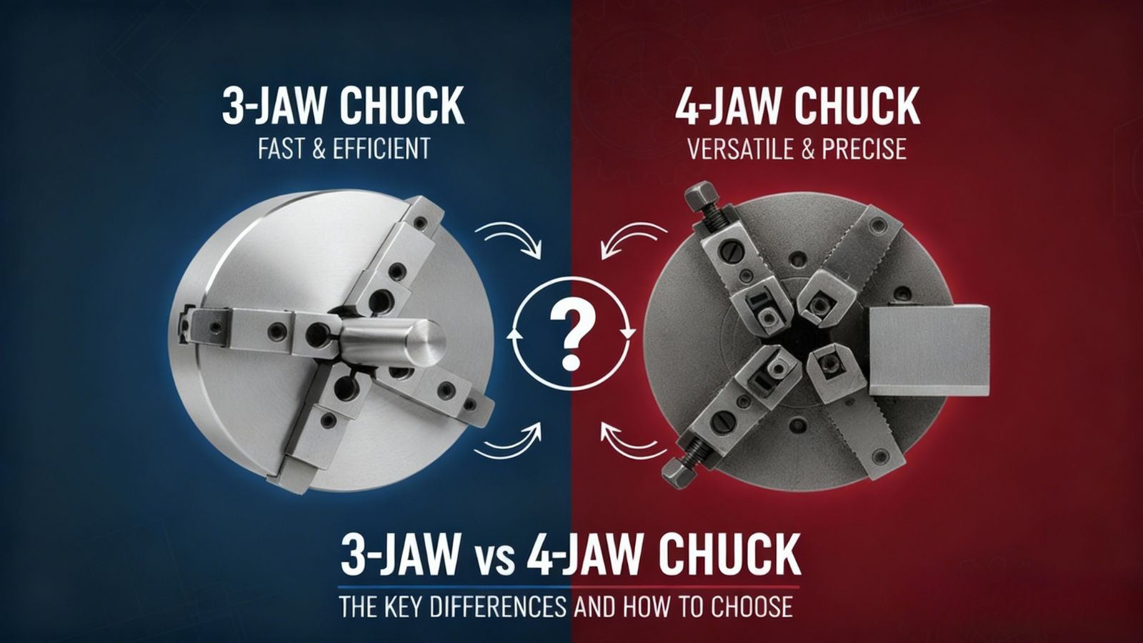
Compare 3-jaw vs 4-jaw chucks for turning operations. Learn the differences in self-centering, precision (runout), setup time, and how to choose the optimal chuck for high-volume or irregular workpieces.


.png)